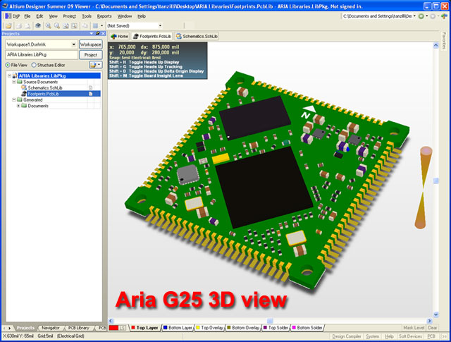

Note the three blue cylindrical capacitors on the right of the board, with a perspective projection their exact position is unclear and their designators can not be seen from the camera position. Press the L shortcut to open the dialog when you are in 3D Layout Mode. To toggle between Perspective and Orthographic projection use the Projection dropdown in the View Configurations dialog. They are dimensionally correct though, they present object geometry precisely, allowing measurements to be take direction in the workspace. Orthographic projections often give the appearance that the object is distorted, so they lack that human realism that perspective projection offers. That is, there is no adjustment for distance from the camera made in these projections, meaning objects on the screen will appear the same size no matter how close or far away they are in reality. Orthographic, or parallel, projections involve no perspective correction. While a perspective projection appears natural, the dimensions of objects in the image are not accurate so cannot be used to perform measurements. This has the effect that distant objects appear smaller than nearer objects, just like real objects appear to the human eye. Perspective projection is a linear projection where three dimensional objects are projected on a picture plane. To switch the board to 3D, press the 3 shortcut or select View » 3D Layout Mode from the menus. The 3D Layout Mode supports 2 types of projection, Perspective and Orthographic, each with their own strengths and weaknesses. Perform measurements directly from the 3D view.Layer examination - switch to single layer mode in 3D.

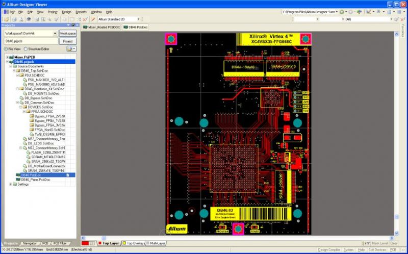
Checking the location and presentation of text strings.Altium Designer's PCB editor can display your board design in glorious 3D, giving you not only a highly realistic view of what the assembled board will look like, but also the ability to perform critical design tasks, including:


 0 kommentar(er)
